
ESP8266 OTA(Over the Air) Updates with Arduino IDE.
OTA (Over the Air) update is the process of loading a new firmware to ESP8266 module using WiFi connection rather than a serial communication.
Uploading a new sketch wirelessly from Arduino IDE is intended for the following typical scenarios:
- during firmware development – as a quicker alternative to uploading a new sketch over a serial
- for updating the firmware of multiple ESPs in your network
Step #1 – Uploading BasicOTA.ino with serial communication
In order to upload firmware to your ESP8266 wirelessly, you have to upload the BasicOTA.ino sketch example first.
Having the latest Arduino IDE software installed from arduino.cc/en/Main/Software. Follow these next instructions:
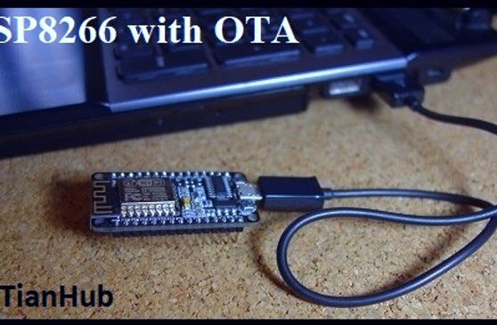
1) Connect your ESP8266 to your computer with a USB cable:(Figure 1.1 shown below).
2) Go to Tools to select your ESP board model. You also have to choose your ESP’s COM port: (Figure 1.2 shown below)
3) Open the BasicOTA.ino example: File > Examples > Arduino OTA > BasicOTA.ino or copy the following sketch to your Arduino IDE.(Download)(Figure 1.3 shown below)
// Created by IoTianHub
#include <ESP8266WiFi.h>

#include <ESP8266mDNS.h>

#include <WiFiUdp.h>

#include <ArduinoOTA.h>


// Replace with your network credentials

const char* ssid = "YOUR_SSID";

const char* password = "YOUR_PASSWORD";


void setup() {

 Serial.begin(115200);

 Serial.println("Booting");

 WiFi.mode(WIFI_STA);

 WiFi.begin(ssid, password);

 while (WiFi.waitForConnectResult() != WL_CONNECTED) {

   Serial.println("Connection Failed! Rebooting...");

   delay(5000);

   ESP.restart();

 }


 // Port defaults to 8266

 // ArduinoOTA.setPort(8266);


 // Hostname defaults to esp8266-[ChipID]

 // ArduinoOTA.setHostname("myesp8266");


 // No authentication by default

 // ArduinoOTA.setPassword((const char *)"123");


 ArduinoOTA.onStart([]() {

   Serial.println("Start");

 });

 ArduinoOTA.onEnd([]() {

   Serial.println("\nEnd");

 });

 ArduinoOTA.onProgress([](unsigned int progress, unsigned int total) {

   Serial.printf("Progress: %u%%\r", (progress / (total / 100)));

 });

 ArduinoOTA.onError([](ota_error_t error) {

   Serial.printf("Error[%u]: ", error);

   if (error == OTA_AUTH_ERROR) Serial.println("Auth Failed");

   else if (error == OTA_BEGIN_ERROR) Serial.println("Begin Failed");

   else if (error == OTA_CONNECT_ERROR) Serial.println("Connect Failed");

   else if (error == OTA_RECEIVE_ERROR) Serial.println("Receive Failed");

   else if (error == OTA_END_ERROR) Serial.println("End Failed");

 });

 ArduinoOTA.begin();

 Serial.println("Ready");

 Serial.print("IP address: ");

 Serial.println(WiFi.localIP());

}


void loop() {

 ArduinoOTA.handle();

}
Note: you have to change the sketch example with your SSID and password.
4) Press the “Upload” button in the Arduino IDE and wait for the “Done uploading” message.(Figure 1.4 shown below)
5) Open the Arduino IDE serial monitor at a baud rate of 115200. If you’ve entered the right network credentials you should see your ESP IP address after a few seconds:(Figure 1.5 shown below)
Step #2 – Uploading a new sketch OTA (Over the Air)
Now your ESP8266 is ready to receive OTA firmware updates. You can unplug your ESP8266 from your computer and power it through any power source (for example a power bank). If your ESP8266 has a wireless connection to your router, you should be fine to upload new firmware.(Figure 2.1 shown below)
1) Go to your Arduino IDE. Open Tools tab select the Port option and you should see something like this: esp8266-xxxxxx at your_esp_ip_address.(Figure 2.2 shown below)
2) Copy the following sketch to your Arduino IDE and upload it to your ESP8266. This sketch blinks the ESP12-E NodeMCU kit built-in LED every second.(Download)
//Created by IoTianHub


#include <ESP8266WiFi.h>

#include <ESP8266mDNS.h>

#include <WiFiUdp.h>

#include <ArduinoOTA.h>


// Replace with your network credentials

const char* ssid = "YOUR_SSID";

const char* password = "YOUR_PASSWORD";


const int ESP_BUILTIN_LED = 2;


void setup() {

  Serial.begin(115200);

  Serial.println("Booting");

  WiFi.mode(WIFI_STA);

  WiFi.begin(ssid, password);

  while (WiFi.waitForConnectResult() != WL_CONNECTED) {

    Serial.println("Connection Failed! Rebooting...");

    delay(5000);

    ESP.restart();

  }


  // Port defaults to 8266

  // ArduinoOTA.setPort(8266);


  // Hostname defaults to esp8266-[ChipID]

  // ArduinoOTA.setHostname("myesp8266");


  // No authentication by default

  // ArduinoOTA.setPassword((const char *)"123");


  ArduinoOTA.onStart([]() {

    Serial.println("Start");

  });

  ArduinoOTA.onEnd([]() {

    Serial.println("\nEnd");

  });

  ArduinoOTA.onProgress([](unsigned int progress, unsigned int total) {

    Serial.printf("Progress: %u%%\r", (progress / (total / 100)));

  });

  ArduinoOTA.onError([](ota_error_t error) {

    Serial.printf("Error[%u]: ", error);

    if (error == OTA_AUTH_ERROR) Serial.println("Auth Failed");

    else if (error == OTA_BEGIN_ERROR) Serial.println("Begin Failed");

    else if (error == OTA_CONNECT_ERROR) Serial.println("Connect Failed");

    else if (error == OTA_RECEIVE_ERROR) Serial.println("Receive Failed");

    else if (error == OTA_END_ERROR) Serial.println("End Failed");

  });

  ArduinoOTA.begin();

  Serial.println("Ready");

  Serial.print("IP address: ");

  Serial.println(WiFi.localIP());

  pinMode(ESP_BUILTIN_LED, OUTPUT);

}


void loop() {

  ArduinoOTA.handle();

  digitalWrite(ESP_BUILTIN_LED, LOW);

  delay(1000);

  digitalWrite(ESP_BUILTIN_LED, HIGH);

  delay(1000);

}
Note: you have to change the sketch example with your SSID and password.
3) Press the “Upload” button in the Arduino IDE and wait for the “Done uploading” message.
4) Your ESP should have it’s built-in LED blinking every second.
Conclusion
I hope this tutorial was useful. Now, you can have your ESP8266 in a remote location and update its firmware without having physical access to the ESP device.
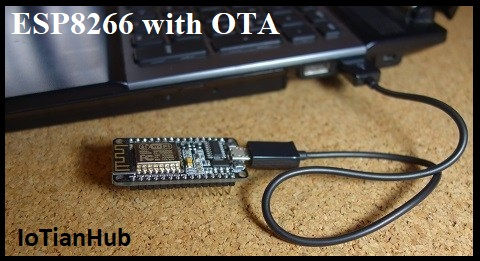
Figure 1.1

Figure 1.2
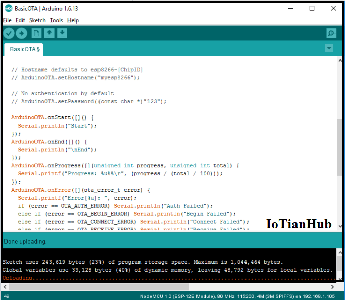
Figure 1.3
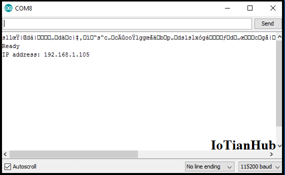
Figure 1.4
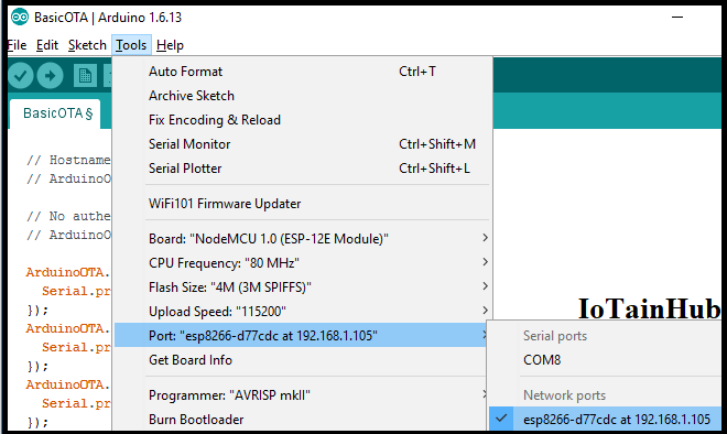
Figure 2.1
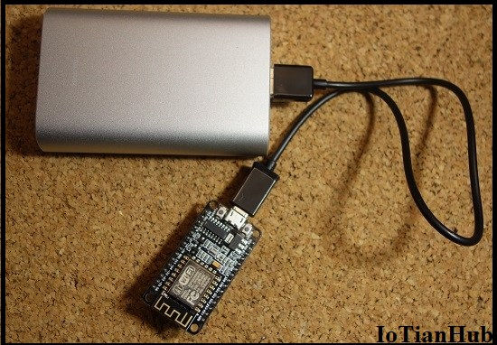
Figure 2.2