
ESP8266 NodeMCU Web Server
The ESP8266 has been a growing star among IoT or WiFi-related projects. It’s an extremely cost-effective WiFi module that – with a little extra effort – can be programmed to build a standalone web server.
What is a Web server and how it works?
Web server is a place which stores, processes and delivers web pages to Web clients. Web client is nothing but a web browser on our laptops and smartphones. The communication between client and server takes place using a special protocol called Hypertext Transfer Protocol (HTTP).(Shown below in figure 1.1)

In this protocol, a client initiates communication by making a request for a specific web page using HTTP and the server responds with the content of that web page or an error message if unable to do so (like famous 404 Error). Pages delivered by a server are mostly HTML documents.
ESP8266 NodeMCU Operating Modes
ESP8266 provides is that it cannot only connect to an existing WiFi network and act as a Web Server, but it can also set up a network of its own, allowing other devices to connect directly to it and access web pages. This is possible because ESP8266 can operate in three different modes: Station mode, Soft Access Point mode, and both at the same time. This provides possibility of building mesh networks we are using Soft Access Point mode.
Soft Access Point (AP) Mode
The ESP8266 that creates its own WiFi network and acts as a hub (Just like WiFi router) for one or more stations is called Access Point (AP). Unlike WiFi router, it does not have interface to a wired network. So, such mode of operation is called Soft Access Point (soft-AP). Also the maximum number of stations that can connect to it is limited to five.(Shown below in figure 1.2)
In AP mode ESP8266 creates a new WiFi network and sets SSID (Name of the network) and IP address to it. With this IP address, it can deliver web pages to all connected devices under its own network.
Connecting LEDs to ESP8266 NodeMCU
Now that we know the basics of how web server works, and in which modes ESP8266 can create a web server, it’s time to connect some LEDs to ESP8266 NodeMCU that we want to control over WiFi.
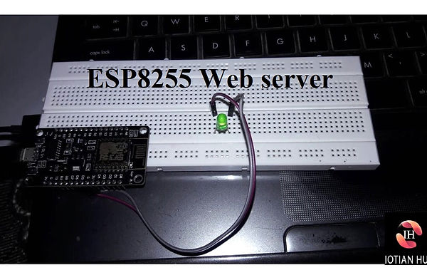
Start by placing the NodeMCU on to your breadboard, ensuring each side of the board is on a separate side of the breadboard. Next, connect two LEDs to digital GPIO D6 and D7 through a 220Ω current limiting resistor.
When you’re done you should have something that looks similar to the illustration shown below figure 1.3.
How to controlling Things From ESP8266 Web Server
So, you might be thinking, “How am I going to control things from a web server that merely processes and delivers web pages?” Well, then you need to understand what’s going on behind the scene.
When you type a URL in a web browser and hit ENTER, the browser sends a HTTP request (a.k.a. GET request) to a web server. It’s a job of web server to handle this request by doing something. You might have figured it out by now that we are going to control things by accessing a specific URL. For example, suppose we entered a URL like http://192.168.1.1/ledon in a browser. The browser then sends a HTTP request to ESP8266 to handle this request. When ESP8266 reads this request, it knows that user wants to turn the LED ON. So, it turns the LED ON and sends a dynamic webpage to a browser showing LED status : ON As easy as Pie!
ESP8266 NodeMCU as HTTP Server using WiFi Access Point (AP) mode
As the heading suggests, this example demonstrates how to turn the ESP8266 into an access point (AP), and serve up web pages to any connected client. To start with, plug your ESP8266 NodeMCU into your computer and Try the sketch out; and then we will dissect it in some detail.
CODE
#include <ESP8266WiFi.h>
#include <ESP8266WebServer.h>
/* Put your SSID & Password */
const char* ssid = "IoTianHub_Server"; // Enter SSID here
const char* password = "asdfgh"; //Enter Password here
/* Put IP Address details */
IPAddress local_ip(192,168,1,1);
IPAddress gateway(192,168,1,1);
IPAddress subnet(255,255,255,0);
ESP8266WebServer server(80);
uint8_t LED1pin = D1;
bool LED1status = LOW;
uint8_t LED2pin = D2;
bool LED2status = LOW;
void setup() {
Serial.begin(115200);
pinMode(LED1pin, OUTPUT);
pinMode(LED2pin, OUTPUT);
WiFi.softAP(ssid, password);
WiFi.softAPConfig(local_ip, gateway, subnet);
delay(100);
server.on("/", handle_OnConnect);
server.on("/led1on", handle_led1on);
server.on("/led1off", handle_led1off);
server.on("/led2on", handle_led2on);
server.on("/led2off", handle_led2off);
server.onNotFound(handle_NotFound);
server.begin();
Serial.println("HTTP server started");
}
void loop() {
server.handleClient();
if(LED1status)
{digitalWrite(LED1pin, HIGH);}
else
{digitalWrite(LED1pin, LOW);}
if(LED2status)
{digitalWrite(LED2pin, HIGH);}
else
{digitalWrite(LED2pin, LOW);}
}
void handle_OnConnect() {
LED1status = LOW;
LED2status = LOW;
Serial.println("GPIO7 Status: OFF | GPIO6 Status: OFF");
server.send(200, "text/html", SendHTML(LED1status,LED2status));
}
void handle_led1on() {
LED1status = HIGH;
Serial.println("GPIO7 Status: ON");
server.send(200, "text/html", SendHTML(true,LED2status));
}
void handle_led1off() {
LED1status = LOW;
Serial.println("GPIO7 Status: OFF");
server.send(200, "text/html", SendHTML(false,LED2status));
}
void handle_led2on() {
LED2status = HIGH;
Serial.println("GPIO6 Status: ON");
server.send(200, "text/html", SendHTML(LED1status,true));
}
void handle_led2off() {
LED2status = LOW;
Serial.println("GPIO6 Status: OFF");
server.send(200, "text/html", SendHTML(LED1status,false));
}
void handle_NotFound(){
server.send(404, "text/plain", "Not found");
}
String SendHTML(uint8_t led1stat,uint8_t led2stat){
String ptr = "<!DOCTYPE html> <html>\n";
ptr +="<head><meta name=\"viewport\" content=\"width=device-width, initial-scale=1.0, user-scalable=no\">\n";
ptr +="<title>LED Control</title>\n";
ptr +="<style>html { font-family: Helvetica; display: inline-block; margin: 0px auto; text-align: center;}\n";
ptr +="body{margin-top: 50px;} h1 {color: #444444;margin: 50px auto 30px;} h3 {color: #444444;margin-bottom: 50px;}\n";
ptr +=".button {display: block;width: 80px;background-color: #1abc9c;border: none;color: white;padding: 13px 30px;text-decoration: none;font-size: 25px;margin: 0px auto 35px;cursor: pointer;border-radius: 4px;}\n";
ptr +=".button-on {background-color: #1abc9c;}\n";
ptr +=".button-on:active {background-color: #16a085;}\n";
ptr +=".button-off {background-color: #34495e;}\n";
ptr +=".button-off:active {background-color: #2c3e50;}\n";
ptr +="p {font-size: 14px;color: #888;margin-bottom: 10px;}\n";
ptr +="</style>\n";
ptr +="</head>\n";
ptr +="<body>\n";
ptr +="<h1>ESP8266 Web Server</h1>\n";
ptr +="<h3>Using Access Point(AP) Mode by IoTianHub</h3>\n";
if(led1stat)
{ptr +="<p>LED1 Status: ON</p><a class=\"button button-off\" href=\"/led1off\">OFF</a>\n";}
else
{ptr +="<p>LED1 Status: OFF</p><a class=\"button button-on\" href=\"/led1on\">ON</a>\n";}
if(led2stat)
{ptr +="<p>LED2 Status: ON</p><a class=\"button button-off\" href=\"/led2off\">OFF</a>\n";}
else
{ptr +="<p>LED2 Status: OFF</p><a class=\"button button-on\" href=\"/led2on\">ON</a>\n";}
ptr +="</body>\n";
ptr +="</html>\n";
return ptr;
}
Accessing the Web Server in AP mode
After uploading the sketch, open the Serial Monitor at a baud rate of 115200. And press the RESET button on ESP8266. If everything is OK, it will show HTTP server started message.(Shown below in figure 1.4)
Next, find any device that you can connect to a WiFi network – phone, laptop, etc. And look for a network called IoTianHub_server. Join the network with password asdfgh.(Shown below in figure 1.5)
After connecting to your NodeMCU AP network, load up a browser and point it to 192.168.1.1 The NodeMCU should serve up a web page showing current status of LEDs and two buttons to control them. If take a look at the serial monitor at the same time, you can see status of NodeMCU’s GPIO pins.(Shown below in figure 1.6)
Now, click the button to turn LED1 ON while keeping an eye on the URL. Once you click the button, the ESP8266 receives a request for /led1on URL. It then turns the LED1 ON and serves a web page with status of LED updated. It also prints the status of GPIO pin on the serial monitor.(Shown below in figure 1.7)
You can test LED2 button and check that it works in a similar way.

figure 1.1
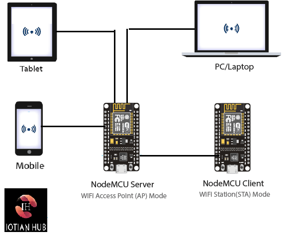
figure 1.2

figure 1.3
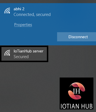
figure 1.4
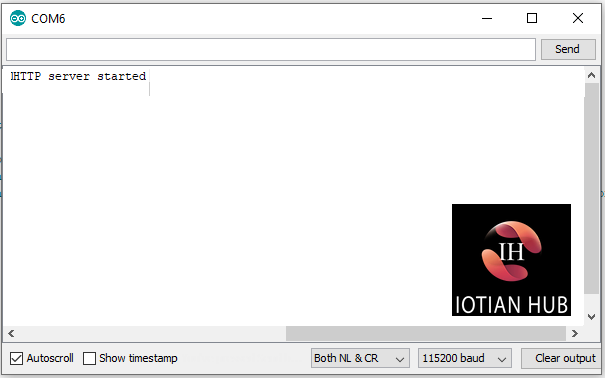
figure 1.5
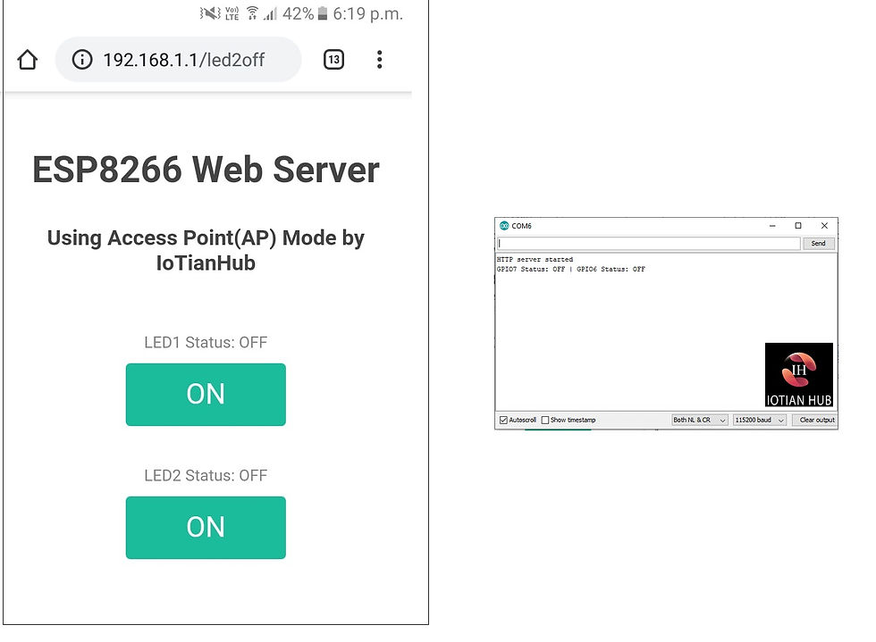
figure 1.6

figure 1.7